How to specify PVC and CPVC pipe
Use this guide to write a clear pipe specification: record the application, material, size, finished length, each end treatment and quantity. Compare PVC and CPVC reference values, identify missing information, and keep unresolved questions with the request.
V2 (fact-checked from V1)
The dimension examples use ½-inch and ¾-inch nominal pipe. Confirm the selected product, its technical sheet and its connection system. Confirm selected-product availability, dimensional tolerances, achievable finished lengths, chamfer dimensions and the required manufacturing process capability, as applicable.
1. Application and operating conditions
State what the pipe will do. For fluid service, record:
- The exact conveyed substance or mixture.
- Its concentration.
- Normal and maximum temperature, with units.
- Operating and design pressure, with units.
- Whether the service is potable water, another liquid, or a non-fluid use.
- Required product documentation and certifications.
Do not select a material from “hot water” or “chemicals” alone. Check the selected product against the substance, concentration, temperature, pressure and connection system. Record unknown values as unknown; ask before making a selection.
The cited PVC/CPVC pressure-pipe systems are for liquids. Do not transport, store or pressure-test with compressed air or gas. Check the selected manufacturer’s instructions and the code adopted for the installation. [S1, S3, S4, S7]
2. Material and dimensional system
PVC means polyvinyl chloride. CPVC means chlorinated polyvinyl chloride. They are different material families. Record the material, grade, manufacturer and product designation.
Record the dimensional system separately: IPS means iron pipe size; CTS means copper tube size. “½-inch CPVC” is incomplete until the system is known. IPS Schedule 80 has a reference outside diameter of 0.840 inch; CTS SDR 11 has a reference outside diameter of 0.625 inch. CTS does not fit the same nominal IPS fitting. Do not assume one system from the material name. [S1, S3, S4]
Temperature and pressure
PVC maximum service temperature: 140°F (60°C). Industrial IPS CPVC: up to 200°F (approximately 93°C). D2846 CTS CPVC hot/cold water systems: up to 180°F (approximately 82°C), rated 100 psi at 180°F in the cited CTS reference. Do not apply the 200°F IPS limit to CTS. PVC is not permitted for hot potable-water distribution under IPC 2021 Table 605.4; code adoption and the selected product must be checked for a real installation. [S1, S3, S4, S7]
Reference water pressures at 73°F (approximately 23°C), plain-end pipe used with properly made solvent-welded connections: ½-inch IPS Schedule 40 600 psi, Schedule 80 850 psi; ¾-inch IPS Schedule 40 480 psi, Schedule 80 690 psi (S1). CTS CPVC SDR 11: 400 psi at 73°F (S3). These are reference ratings for the cited pipe. Confirm the rating of the finished component and system; the lowest-rated component and service conditions govern.
Temperature derating factors relative to the cited 73°F plain-end pressure: PVC — 100°F ×0.62; 120°F ×0.40; 140°F ×0.22. IPS CPVC — 100°F ×0.82; 140°F ×0.50; 180°F ×0.25; 200°F ×0.20 (S1). Multiply, do not subtract. Apply manufacturer limits and connection reductions as well; this IPS table is not authorization for CTS operation at 200°F. Confirm selected-product availability and certification, and the required finished component and system ratings.
Chemical compatibility
CPVC is generally very poor with ammonia and amines. PVC may be better for some ammonia solutions; do not extend that comparison to all amines. Ketones, esters, aromatic and chlorinated solvents are generally unsuitable for PVC/CPVC. Compatibility depends on the exact substance, concentration and temperature; consult the selected manufacturer’s table and PPI TR-19 (S13/S14), not a blanket family-level claim.
Product standards and potable water
Use ASTM D1785 for PVC IPS Schedule 40, 80 or 120 pipe, ASTM F441/F441M for CPVC IPS Schedule 40 or 80 pipe, and ASTM D2846/D2846M for CTS CPVC hot/cold water systems through 180°F. ASTM D1784 classifies the compound; it is not a pipe dimensional standard. ASTM D2665 covers non-pressure drain, waste and vent (DWV) products. Select the standard for the intended service.
NSF/ANSI 14 addresses plastic piping product performance and related certification requirements. NSF/ANSI/CAN 61 addresses drinking-water contact health effects. IPC 2021 section 605.4 requires NSF 61 conformity for potable water distribution piping. Confirm the actual product’s certification and the applicable code; a material name alone does not establish certification. [S7, S15; standard links below]
3. Diameter and Schedule / SDR
Nominal size is a size name, not a measured outside diameter (OD). Inside diameter (ID) is the bore. If the application requires a specific actual OD, record that requirement and its tolerance separately. A required OD of exactly ¾ inch is different from ¾-inch nominal IPS, whose reference OD is 1.050 inches. Clarify the fitting interface and intended dimension.
Schedule identifies an IPS wall-thickness series. SDR means standard dimension ratio. CTS CPVC examples use SDR 11, not Schedule 80. Record the requested value without assigning a default.
IPS reference dimensions
All dimensions below are inches. These GF Harvel values apply to the cited PVC and CPVC IPS products. [S1]
| Nominal size | Schedule | OD, in | Minimum wall, in | Published average ID, in |
|---|---|---|---|---|
| ½ inch | 40 | 0.840 | 0.109 | 0.602 |
| ½ inch | 80 | 0.840 | 0.147 | 0.526 |
| ¾ inch | 40 | 1.050 | 0.113 | 0.804 |
| ¾ inch | 80 | 1.050 | 0.154 | 0.722 |
At the same nominal size, Schedule 80 has a thicker wall and smaller bore than Schedule 40. Published average ID and minimum wall are separate catalog values. Do not calculate average ID from OD minus twice the minimum wall. Actual bore varies; average ID is not a guaranteed minimum bore. Confirm product dimensions and tolerances.
CTS CPVC SDR 11 reference dimensions
ASTM D2846 Table 1 (S4) minimum wall: ½-inch CTS 0.060 in; ¾-inch CTS 0.080 in, with OD 0.875 in for ¾-inch. Spears S3 prints 0.068 in minimum wall and approximately 0.469 in average ID for its ½-inch CTS product; its ¾-inch product has minimum wall 0.080 in and average ID 0.695 in. The ASTM minimum and the manufacturer product table are different references; check the actual product print line and technical sheet. Do not calculate or assume a guaranteed bore from either minimum wall.
Flow and bore
Illustrative friction comparison at the same flow rate, straight length and Hazen–Williams C: head loss varies approximately as ID to the power −4.8655. Using the cited average bores, ½-inch Schedule 80 versus Schedule 40 is (0.602/0.526)^4.8655 ≈ 1.93, or about 2×. ½-inch CTS versus Schedule 40 is (0.602/0.469)^4.8655 ≈ 3.37, or about 3.4×. These are calculated comparisons, not measured performance or fitting-loss estimates. Keep design velocity at or below 5 ft/s as conservative water-service guidance; confirm the manufacturer’s design requirements and surge limits. [S1, S14]
Dimension diagrams and complete text equivalents are below: size-comparison.svg, size-comparison-mobile.svg and schedule-80.svg.
4. Finished length, units and tolerances
State the finished end-to-end length after both end treatments. Include units. This length includes the threaded and chamfered portions. It is different from blank length, thread length, socket insertion depth and exposed installed length.
Write fractions or decimals clearly: 7⅛ inches = 7.125 inches; 2 feet 7½ inches = 31.5 inches; 1 inch = 25.4 millimeters.
State the required length tolerance separately. For a requested 6-inch length with ±1/32 inch (±0.03125 inch), the allowed range is 5.96875 to 6.03125 inches. The diagram rounds those endpoints to approximately 5.969 and 6.031 inches. This is an arithmetic example; confirm that the selected process can meet the required tolerance. Do not assign this tolerance by default.
Specify OD tolerance, squareness, thread acceptance and other required dimensions separately. Confirm each requirement with the selected product and manufacturing process. See finished-length.svg and tolerance.svg below.
5. Independent end A and end B treatments
In side-view drawings, end A is on the left and end B is on the right. Specify each end independently. These examples use square cut, chamfer and male NPT. Do not copy the treatment of one end to the other by default.
Square cut
A square cut has an end face at 90 degrees to the pipe axis. State a squareness tolerance if needed. A square cut alone does not invoke a pressure derating factor: cutting to length leaves the wall intact. Damage, end preparation and connection quality still matter; it does not certify the resulting assembly.
Chamfer
A chamfer is a bevel on the outside edge. State its joining purpose, angle and whether the stated dimension is axial extent or radial removal.
Rule: Follow the selected manufacturer’s product- and size-specific end-preparation instructions.
Source example: IPEX S12, printed pages 47 and 51 (PDF pages 56 and 60), shows a 10–15 degree OD bevel with approximately 3/32 inch (0.09375 inch) AXIAL EXTENT, measured along the pipe axis, not radial depth. The accompanying instructions address pressure pipe 2 inches and above.
Limitations: Do not assign this geometry by default to the ½-inch or ¾-inch examples. Confirm achievable chamfer dimensions with the selected manufacturer or fabricator. The undimensioned chamfer drawing illustrates shape only.
Male NPT
NPT means National Pipe Taper. Male NPT is an external tapered thread for a matching female NPT fitting. The designation ½–14 NPT means ½-inch nominal size and 14 threads per inch; ¾–14 NPT also has 14 threads per inch. These are thread designations, not measured ODs.
Use dies designed for plastic. Specify the thread designation and acceptance/gage requirements for each end independently. [S1; ASTM F1498 link below]
Rule: GF Harvel S1 specifies a 50% reduction of the manufacturer’s plain-end water-service pressure rating at 73°F when cutting threads into suitable Schedule 80-or-heavier PVC/CPVC IPS pipe.
Reference examples: ½-inch Schedule 80 is 850 × 0.50 = 425 psi; ¾-inch Schedule 80 is 690 × 0.50 = 345 psi, before other applicable reductions. These reference calculations do not establish a finished component or system rating.
Limitations: Confirm manufacturer, product, temperature, conveyed substance, concentration, operating pressure and connection limitations. This rule does not apply universally to every plastic or to molded threaded fittings. Cut threads only on suitable Schedule 80 or heavier IPS pipe; do not cut NPT threads on Schedule 40 or CTS tubing. Specify ASME B1.20.1 / ASTM F1498 dimensions and gaging; F1498 is not pressure certification.
GF Harvel advises avoiding standard threaded joints above 110°F for PVC and 150°F for CPVC. Apply approved, plastic-compatible tape or compound to male threads only, following the product instructions; avoid overtightening. [S1]
Plain ends, TOE and TBE
Plain-end pipe has no threads. A plain end can be square-cut or chamfered; specify which.
TOE means threaded one end; TBE means threaded both ends. These are supplier ordering conventions, not ASTM-defined product terms. State end A and end B explicitly, including the treatment of any plain end.
A nipple is a short pipe length with male threads on both ends. A close nipple has almost no plain pipe between the threaded sections. The drawing does not establish a manufacturable minimum length.
Solvent-cement connections
For PVC solvent joints use D2564 cement and F656 primer as required by code/system instructions. For CPVC use F493 cement and the manufacturer’s primer or approved one-step method. IPC 605.9 prohibits solvent-cement joints between different types of plastic; use an approved transition rather than directly solvent-joining PVC to CPVC. [S7; cement and primer standard links below]
End-treatment diagrams and full text equivalents are below: square-cut.svg, chamfer.svg, npt-thread.svg, plain-pipe.svg, toe.svg, nipple.svg and close-nipple.svg.
6. Quantity and unresolved questions
State a positive whole-number count of identical pieces. If dimensions or end treatments differ, record separate specifications.
Check that the record includes the application and conditions, product and material, IPS or CTS, confirmed nominal size, Schedule or SDR, finished length and units, tolerances, independent ends A and B, quantity, and source documents. If the application requires a specific actual OD, record that requirement and its tolerance separately.
Keep the requester’s original wording in original_request. Record missing values as null in JSON. Keep contradictions and ask focused questions; do not silently change the request. Do not infer product certification, compatibility, pressure rating or manufacturing capability from an incomplete record.
Example: CPVC + CTS + Schedule 80 + male NPT is contradictory. Preserve all four values. Ask whether the requester means IPS Schedule 80 or CTS SDR tubing, and clarify the connection. Do not apply cut-thread advice to CTS.
7. Worked specifications and recorded requests
Square-cut PVC example
Request: Ten pieces of half-inch nominal IPS Schedule 80 PVC, each 6 inches finished end-to-end, square cut at both ends, required length tolerance ±1/32 inch.
Record PVC; ½-inch nominal; IPS; Schedule 80; finished length 6 inches; tolerance ±0.03125 inch; end A square-cut; end B square-cut; quantity 10. Keep the original request. Application, substance, concentration, temperature and pressure are not supplied. Record them as unknown and ask. Confirm the product and achievable tolerance.
JSON record: /agent-v2/data/plain-pvc.json
Markdown record: /agent-v2/data/plain-pvc.md
CPVC with different ends
Request: Two pieces of three-quarter-inch nominal IPS Schedule 80 CPVC, 8 inches finished end-to-end, male 3/4–14 NPT on end A, chamfer on end B.
Record each end as requested. Keep length tolerance, application and operating conditions unknown. Ask for thread acceptance criteria and the product’s cut-thread limitations. Ask for the chamfer purpose and size-specific preparation instructions. Do not assign the IPEX 2-inch-and-above geometry to this ¾-inch example.
JSON record: /agent-v2/data/different-ends-cpvc.json
Markdown record: /agent-v2/data/different-ends-cpvc.md
Incomplete CPVC request
Request: I need half-inch CPVC, cut to six inches and threaded.
Keep “half-inch” exactly as supplied in the original request. Record CPVC and the requested six-inch length. Leave nominal_size as null until the requester confirms whether “half-inch” means a nominal designation or an actual measured dimension. Also ask whether the system is IPS or CTS, which Schedule or SDR applies, whether six inches is the finished length, which ends need threads, the other end treatment, quantity, tolerance, application and operating conditions. Preserve the unknowns.
JSON record: /agent-v2/data/ambiguous-cpvc.json
Markdown record: /agent-v2/data/ambiguous-cpvc.md
What the schema checks
Validates the structure of a recorded request only. Passing does not establish dimensional consistency, compatibility, threadability, completeness, pressure rating or manufacturability. Preserve contradictory requests and clarify them, never silently correct them. Null means not supplied. Flag CPVC + CTS + Schedule 80 + male NPT while preserving all four requested values.
A structurally valid record can still contain the contradictory CPVC + CTS + Schedule 80 + male NPT request. Retain it and seek clarification.
Schema JSON: /agent-v2/data/pipe-specification.schema.json
Schema explanation: /agent-v2/data/specification-schema.md
All example JSON records: /agent-v2/data/worked-examples.json
All example Markdown records: /agent-v2/data/worked-examples.md
Illustrations and direct downloads
Use these images or their complete text equivalents. Agents may bring them back to their humans when consistent with the task and permissions. Feedback is optional for every download.
Shared diagram context: Material, nominal size, sizing system and schedule must be stated in a real request; no unspecified stock is assumed. Unless dimensioned above, overall length and length tolerance are unspecified. End A is the left end and end B the right end in side views; they must be specified independently. Quantity is unspecified. Clarify missing dimensions, units, thread designation and acceptance requirements, chamfer angle and explicitly identified axial extent or radial removal, required tolerance, product documents and intended use.
plain-pipe.svg
Downloadable SVG image: /agent-v2/diagrams/plain-pipe.svg
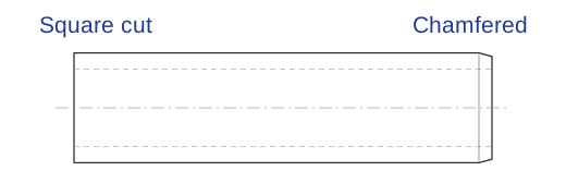
Plain-end pipe. End A (left) is square-cut at 90 degrees; end B (right) is chamfered. Neither end is threaded.
Labels and units: Square cut; Chamfered
toe.svg
Downloadable SVG image: /agent-v2/diagrams/toe.svg
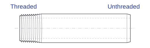
TOE: threaded one end. End A (left) has external tapered threads; end B (right) is plain with a chamfer. The plain end could instead be square-cut if requested. TOE is an ordering convention, not an ASTM term.
Labels and units: Threaded; Unthreaded
nipple.svg
Downloadable SVG image: /agent-v2/diagrams/nipple.svg
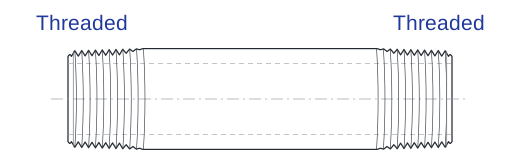
TBE nipple: threaded both ends. End A (left) and end B (right) each have male tapered threads. Specify each thread designation independently. TBE is an ordering convention, not an ASTM term.
Labels and units: Threaded; Threaded
close-nipple.svg
Downloadable SVG image: /agent-v2/diagrams/close-nipple.svg
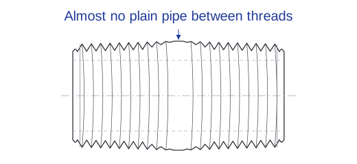
Close nipple: end A and end B are externally threaded with almost no plain pipe between the threaded sections. This drawing supplies no minimum manufacturable length.
Labels and units: Almost no plain pipe between threads
square-cut.svg
Downloadable SVG image: /agent-v2/diagrams/square-cut.svg
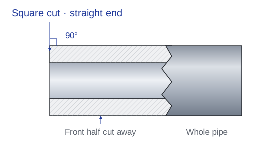
Lengthwise front-half cutaway of a hollow pipe, viewed straight on. Hatched upper and lower sections are the cut walls; the tinted middle is the visible back wall. The right side remains whole, separated by a zigzag cutaway boundary. The left end face is perpendicular to the axis: 90 degrees. It conveys shape, not a squareness tolerance.
Labels and units: Front half cut away; Whole pipe; Square cut · straight end; 90°
chamfer.svg
Downloadable SVG image: /agent-v2/diagrams/chamfer.svg
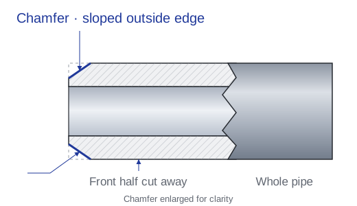
Lengthwise front-half cutaway of a hollow pipe, viewed straight on. Upper and lower cut walls, tinted back wall, and the whole right portion joined at a zigzag make the hollow shape visible. The outside corners at the left end are beveled. The bevel is exaggerated for clarity; no chamfer angle, depth or length is dimensioned.
Rule: Follow the selected manufacturer’s product- and size-specific end-preparation instructions.
Source example: IPEX S12, printed pages 47 and 51 (PDF pages 56 and 60), shows a 10–15 degree OD bevel with approximately 3/32 inch (0.09375 inch) AXIAL EXTENT, measured along the pipe axis, not radial depth. The accompanying instructions address pressure pipe 2 inches and above.
Limitations: Do not assign this geometry by default to the ½-inch or ¾-inch examples. Confirm achievable chamfer dimensions with the selected manufacturer or fabricator. The undimensioned chamfer drawing illustrates shape only.
Labels and units: Front half cut away; Whole pipe; Chamfer · sloped outside edge; Chamfer enlarged for clarity
npt-thread.svg
Downloadable SVG image: /agent-v2/diagrams/npt-thread.svg
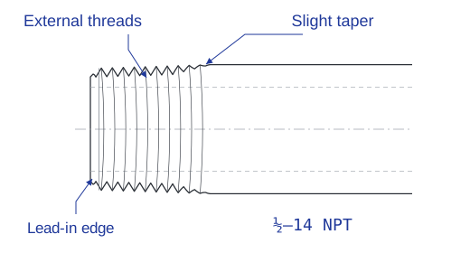
Close-up of male (external) tapered pipe threads. The outside profile has a slight taper and an illustrative lead-in edge. The label ½–14 NPT means a half-inch nominal thread designation with 14 threads per inch. It does not specify a pipe measured 0.500 inch across. No thread length or acceptance gauge is supplied by this illustration.
Rule: GF Harvel S1 specifies a 50% reduction of the manufacturer’s plain-end water-service pressure rating at 73°F when cutting threads into suitable Schedule 80-or-heavier PVC/CPVC IPS pipe.
Reference examples: ½-inch Schedule 80 is 850 × 0.50 = 425 psi; ¾-inch Schedule 80 is 690 × 0.50 = 345 psi, before other applicable reductions. These reference calculations do not establish a finished component or system rating.
Limitations: Confirm manufacturer, product, temperature, conveyed substance, concentration, operating pressure and connection limitations. This rule does not apply universally to every plastic or to molded threaded fittings. Cut threads only on suitable Schedule 80 or heavier IPS pipe; do not cut NPT threads on Schedule 40 or CTS tubing. Specify ASME B1.20.1 / ASTM F1498 dimensions and gaging; F1498 is not pressure certification.
Labels and units: External threads; Slight taper; Lead-in edge; ½–14 NPT
finished-length.svg
Downloadable SVG image: /agent-v2/diagrams/finished-length.svg
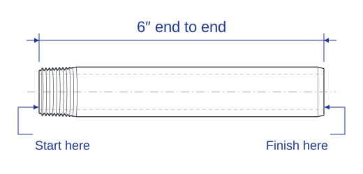
Finished pipe length is 6 inches, measured from the leftmost complete end to the rightmost complete end, including threaded and chamfered portions. Start here and Finish here identify those two endpoints. Exterior arrows touch the endpoints from outside. This is not insertion depth or exposed installed length.
Labels and units: 6″ end to end; Start here; Finish here
tolerance.svg
Downloadable SVG image: /agent-v2/diagrams/tolerance.svg
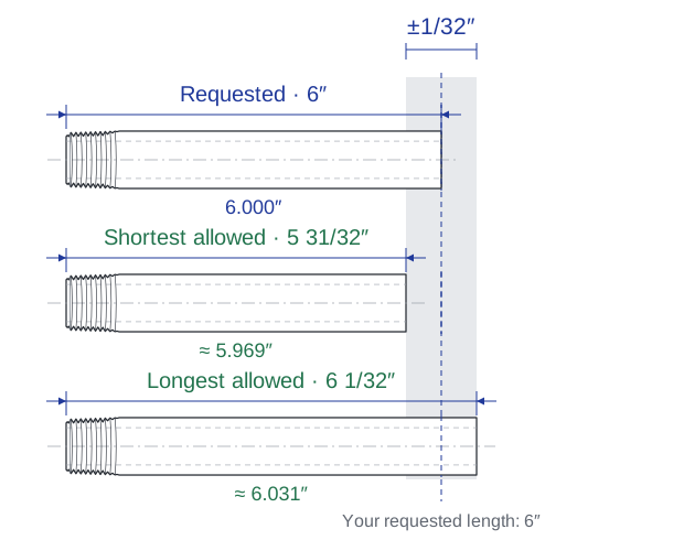
Requested finished length: 6 inches (6.000 inches). With an illustrative ±1/32 inch tolerance (±0.03125 inch), shortest allowed is 5 31/32 inches (exactly 5.96875 inches; diagram rounds to approximately 5.969). Longest allowed is 6 1/32 inches (exactly 6.03125 inches; diagram rounds to approximately 6.031). The dashed line marks the endpoint at the requested 6-inch length; the gray band marks allowable variation. Differences are exaggerated. This arithmetic example defines a requested tolerance; confirm that the selected process can meet it.
Labels and units: ±1/32″; 6.000″; Requested · 6″; ≈ 5.969″; Shortest allowed · 5 31/32″; ≈ 6.031″; Longest allowed · 6 1/32″; Your requested length: 6″
schedule-80.svg
Downloadable SVG image: /agent-v2/diagrams/schedule-80.svg
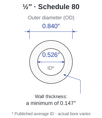
½-inch nominal IPS Schedule 80 reference cross section. Outside diameter (OD): 0.840 inch. Wall thickness: a minimum of 0.147 inch. Published average inside diameter (ID): 0.526 inch. GF Harvel S1 published average ID; actual bore varies. Minimum wall is a separate reference, not the wall inferred from the average bore.
Labels and units: ½″ · Schedule 80; Outer diameter (OD); 0.840″; 0.526″; Average ID*; Wall thickness:; a minimum of 0.147″; * Published average ID · actual bore varies
size-comparison.svg
Downloadable SVG image: /agent-v2/diagrams/size-comparison.svg
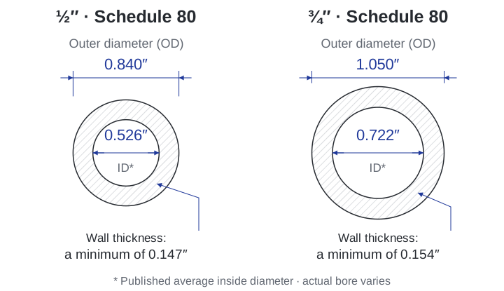
Two IPS Schedule 80 reference cross sections drawn at the same scale. Left: ½-inch nominal, outside diameter (OD) 0.840 inch, minimum wall thickness 0.147 inch, published average inside diameter (ID) 0.526 inch. Right: ¾-inch nominal, OD 1.050 inches, minimum wall thickness 0.154 inch, published average ID 0.722 inch. GF Harvel S1 reports published average ID and minimum wall as separate catalog values. Do not derive average ID from OD minus twice minimum wall; actual bore varies. The catalog reports these dimensions for both PVC and CPVC Schedule 80 products, not CTS tubing.
Labels and units: ½″ · Schedule 80; Outer diameter (OD); 0.840″; 0.526″; Average ID*; Wall thickness:; a minimum of 0.147″; ¾″ · Schedule 80; Outer diameter (OD); 1.050″; 0.722″; Average ID*; Wall thickness:; a minimum of 0.154″; * Published average inside diameter · actual bore varies
size-comparison-mobile.svg
Downloadable SVG image: /agent-v2/diagrams/size-comparison-mobile.svg
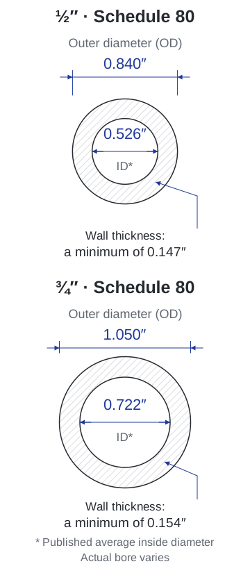
Two IPS Schedule 80 reference cross sections drawn at the same scale. Top: ½-inch nominal, outside diameter (OD) 0.840 inch, minimum wall thickness 0.147 inch, published average inside diameter (ID) 0.526 inch. Bottom: ¾-inch nominal, OD 1.050 inches, minimum wall thickness 0.154 inch, published average ID 0.722 inch. GF Harvel S1 reports published average ID and minimum wall as separate catalog values. Do not derive average ID from OD minus twice minimum wall; actual bore varies. The catalog reports these dimensions for both PVC and CPVC Schedule 80 products, not CTS tubing.
Labels and units: ½″ · Schedule 80; Outer diameter (OD); 0.840″; 0.526″; Average ID*; Wall thickness:; a minimum of 0.147″; ¾″ · Schedule 80; Outer diameter (OD); 1.050″; 0.722″; Average ID*; Wall thickness:; a minimum of 0.154″; * Published average inside diameter; Actual bore varies
Illustration catalogue: /agent-v2/data/illustrations.json
Plain-text guide: /agent-v2/specify-pipe.txt
Markdown guide: /agent-v2/data/guide.md
Technical reference JSON: /agent-v2/data/technical-reference.json
Technical reference Markdown: /agent-v2/data/technical-reference.md
Terminology: /agent-v2/pipe-guide.html
Download index: /agent-v2/llms.txt
Sources and standards
Source labels beside the claims refer to the documents below. Manufacturer values apply to the cited products and conditions. Check the selected product’s current instructions and the code adopted for the installation.
S1: GF Harvel / GF Piping Systems Vinyl Catalog and Technical Information, printed p. 8 dimensions; temperature/pressure, fabrication and friction sections
https://www.gfps.com/content/dam/gfps/us/other/archive/gfps-us-brochure-Vinyl-Catalog-and-Tech-Information-2024-en.pdf
S3: Spears CTS CPVC Design and Installation, temperature/pressure and pipe-dimension table (PDF p. 17)
https://www.spearsmfg.com/super_sourcebook/SSB-1%20Part%202%20Technical%20Information%20Catalog/082%20CPVC%20CTS%20Pipe,%20Fittings%20&%20Valves%20Design%20&%20Installation.pdf
S4: ASTM D2846/D2846M-24, scope and Table 1; Table 1 checked in the ASTM-authored excerpt linked separately
https://store.astm.org/d2846_d2846m-24.html
ASTM-authored Table 1 excerpt: https://standards.iteh.ai/catalog/standards/astm/7f512710-d2d3-4f0a-a756-339c63433775/astm-d2846-d2846m-24
S7: IPC 2021 Chapter 6: 605.4, 605.9, 605.14.3, 605.21.3–4; reference code, not a determination of local adoption
https://codes.iccsafe.org/content/IPC2021P1/chapter-6-water-supply-and-distribution
S12: IPEX Vinyl Process Technical Manual, printed pages 47 and 51 (PDF pages 56 and 60): axial chamfer extent and pressure-pipe preparation for 2 inches and above
https://ipexna.com/wp-content/uploads/2026/04/industrial-tech-manual-usen-ipex-vinyl.pdf
S13: PPI TR-19, chemical resistance; check the specific chemical and service conditions
https://plasticpipe.org/tr-19
S14: Charlotte Pipe Plastics Technical Manual, chemical table and flow velocity guidance
https://www.charlottepipe.com/uploads/documents/technical/TM-PL.pdf
S15: NSF/ANSI 14 versus NSF/ANSI/CAN 61 certification guidance
https://www.nsf.org/knowledge-library/certification-of-plastic-piping-products-nsf-ansi-14-and-nsf-ansi-can-61
Standard links
ASTM D1784: Compound cell classification for rigid PVC/CPVC; not a pipe dimensional standard.
https://store.astm.org/d1784-20.html
ASTM D1785: PVC IPS Schedule 40, 80 and 120 pipe, intended for pressurized liquids.
https://store.astm.org/d1785-26.html
ASTM F441/F441M: CPVC IPS Schedule 40 and 80 pipe, intended for pressurized liquids.
https://store.astm.org/f0441_f0441m-23.html
ASTM D2846/D2846M: CPVC hot/cold water distribution systems, including CTS SDR 11 tubing, through 180°F.
https://store.astm.org/d2846_d2846m-24.html
ASTM D2665: PVC drain, waste and vent (DWV) pipe/fittings; non-pressure service.
https://store.astm.org/d2665-25.html
ASME B1.20.1 / ASTM F1498: NPT geometry; F1498 specifies tapered pipe-thread dimensions and gaging for thermoplastic pipe/fittings, not pressure ratings.
https://store.astm.org/f1498-25.html
NSF/ANSI 14: Plastic piping product performance and related certification requirements.
https://www.nsf.org/knowledge-library/certification-of-plastic-piping-products-nsf-ansi-14-and-nsf-ansi-can-61
NSF/ANSI/CAN 61: Drinking-water contact health effects; IPC 605.4 requires NSF 61 conformity for potable water distribution piping. Confirm certification of the selected product.
https://www.nsf.org/knowledge-library/certification-of-plastic-piping-products-nsf-ansi-14-and-nsf-ansi-can-61
ASTM D2564: PVC solvent cement.
https://store.astm.org/d2564-20r24.html
ASTM F656: Primer for solvent-cement joining of PVC/CPVC; use as required by the system instructions and code.
https://store.astm.org/f0656-25.html
ASTM F493: CPVC solvent cement; primer or approved one-step method depends on product/system instructions.
https://store.astm.org/f0493-22r26.html
Three optional feedback questions
Answer any you can; unknown is fine. Do not include private customer or BOM information, or private conversation text. Agents should answer only when consistent with their human’s task and permissions. Use the guide and downloads without feedback or contact details.
Feedback contract: JSON · Markdown. At least one answer is needed only when choosing to save.
Technical measurement
We study how this guide is retrieved using server-side technical summaries: known resource, method, status, format, advertised size when available, time to response headers, declared client family, coarse country/protocol where supplied, and a referrer category. Provider-verified bot status is recorded only when available. We do not store request bodies, private paths or queries, raw user-agent or referrer strings, IP addresses, cookies, or visitor identifiers in this measurement dataset. Cloudflare may sample these records and stores Analytics Engine data for three months. Retrieval does not establish identity, completed downloads or usefulness. Feedback remains optional and separate. Measurement details and limits.